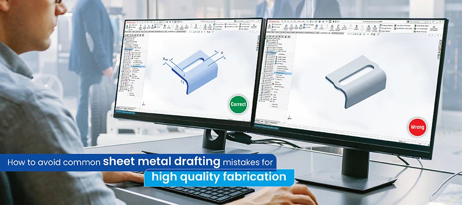
Mistakes in sheet metal drafting lead to fabrication errors. These errors stem from inaccurate material properties, incorrect dimensioning, improper bend allowances, and misaligned grain direction. This article provides tips and best practices for sheet metal design in CAD to help you avoid these common pitfalls.
Mistakes in sheet metal drafting, such as incorrect dimensions, missing bend radii, or unclear tolerances, result in incorrectly manufactured parts. This frequently necessitates rework or even scrapping, impacting resources and project deadlines.
The key to avoiding sheet metal errors starts with attention to detail during the design phase.
A sheet metal drafter must possess a thorough understanding of sheet metal properties and manufacturing processes. Consider a standardized drafting system, and use templates to help minimize inconsistencies in your designs.
Implement regular peer reviews and design checks to identify potential problems before fabrication begins. Clear and open communication between designers and fabricators is crucial to ensure everyone interprets the drawings accurately.
In this article, we discuss the common mistakes in sheet metal designing and provide drafting tips to improve the accuracy of your sheet metal designs streamline your fabrication process and enhance the quality of your products.
How mistakes in sheet metal drafting impact fabrication
Sheet metal drafting mistakes increase costs, cause production delays and lower the quality of the final product.
Let’s examine these issues in detail:
• Increased material waste: Inaccurate dimensions, incorrect bend allowances, or poorly placed holes result in wasted material, increasing costs and negatively impacting the environment.
• Rework and scrap: When parts don’t meet specifications due to drafting errors, they often require rework or, in the worst cases, become scrap altogether. This adds time and labor costs to the project.
• Production delays: Errors in drawings cause confusion and delays, causing production halts to clarify discrepancies.
• Compromised part quality: Incorrectly specified bend radii, missing bend relief, or disregard for grain direction lead to parts with cracks, deformations or weakened structural integrity.
• Assembly issues: Drafting errors cause sheet metal components to not fit together correctly during assembly. This causes problems in downstream processes and compromises the final product’s functionality.
Common sheet metal drafting mistakes and design guidelines to avoid them
Understanding drafting errors enables drafters and engineers to prioritize accuracy and precision. This proactive approach streamlines fabrication, reduces costs, and ensures high-quality end products.
Here, we take a look at some common drafting errors and how you can avoid them:
• Overlooking bend radius and K-factor
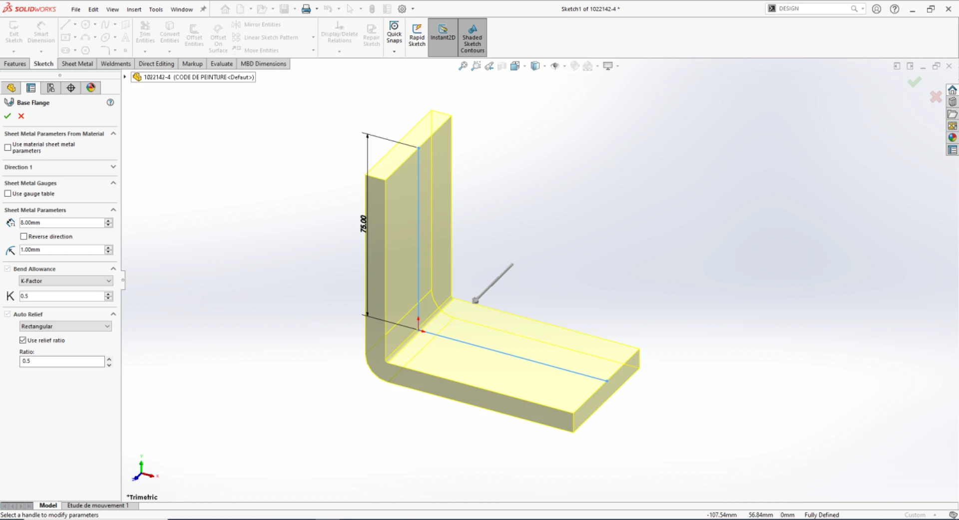
One of the most common sheet metal drafting mistakes is neglecting the bend radius and the K-factor. The bend radius refers to the inside curvature of the bend, while the K-factor represents the ratio of the neutral axis location to the material thickness.
Failing to account for these factors results in inaccurate part dimensions and springback issues after bending.
How to avoid
• Always consider the material’s minimum bend radius to prevent cracking or deformation during bending
• Utilize the appropriate K-factor for the chosen material and bending process to ensure accurate bend allowance calculations
• Consult material property charts and utilize 3D CAD modeling features of software like AutoCAD, SolidWorks to automate bend allowance calculations
• Ignoring grain direction
Sheet metal exhibits anisotropic properties, meaning its strength and ductility vary with the grain structure's direction. Bending parallel to the grain leads to cracking and uneven deformation, compromising the part’s integrity.
For example, when designing a door panel with a long, shallow bend along its length, if the sheet metal grain runs parallel to this bend, the panel might crack along the bend, or the bend could become wavy and distorted.
How to avoid
• Show the grain direction on the drawing to guide the fabricator
• Design parts to be bent perpendicular to the grain for improved strength and bend quality
• Consider alternative manufacturing processes like hydroforming for complex shapes requiring bending parallel to the grain
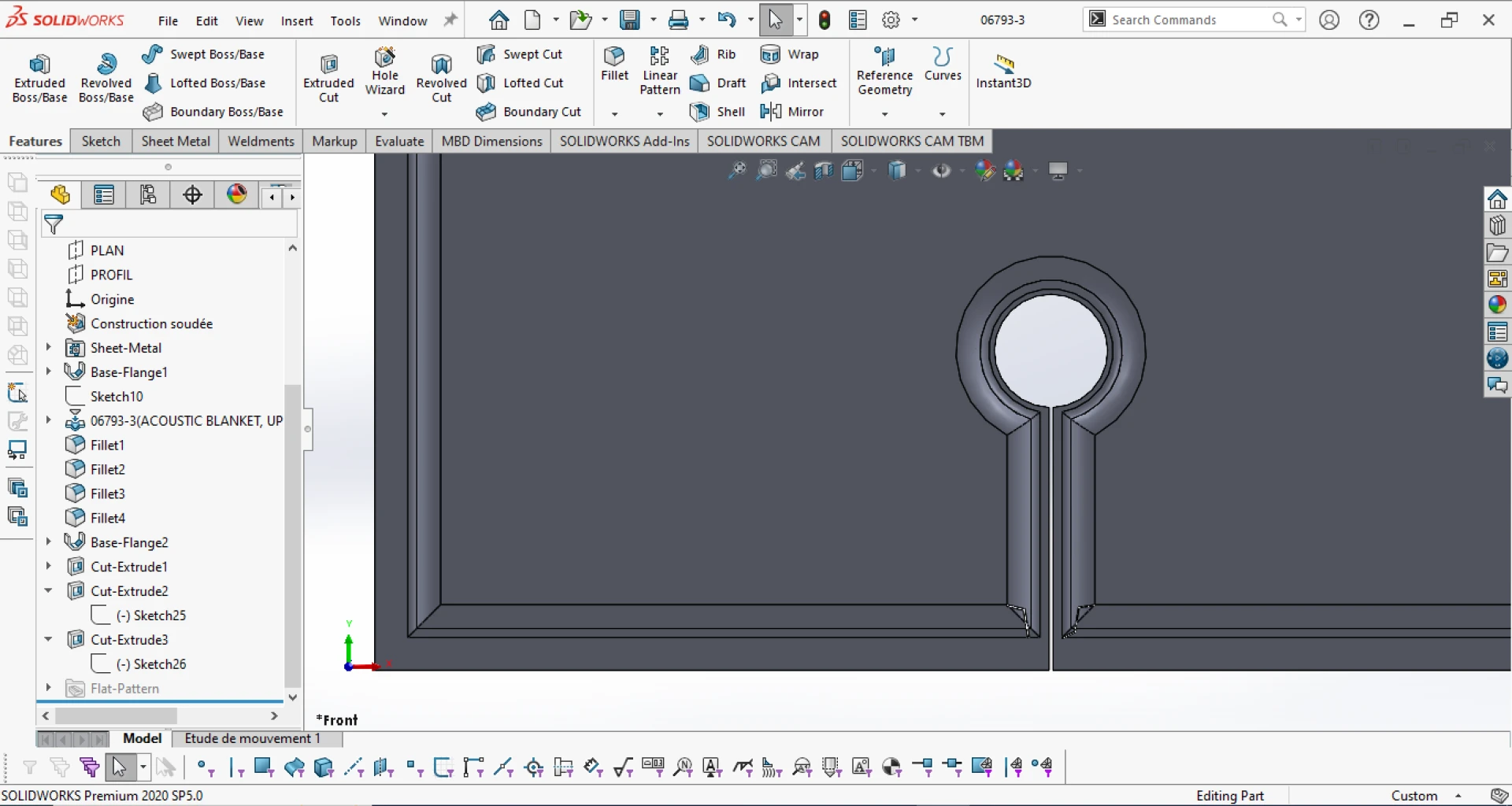
• Incorrect hole placing
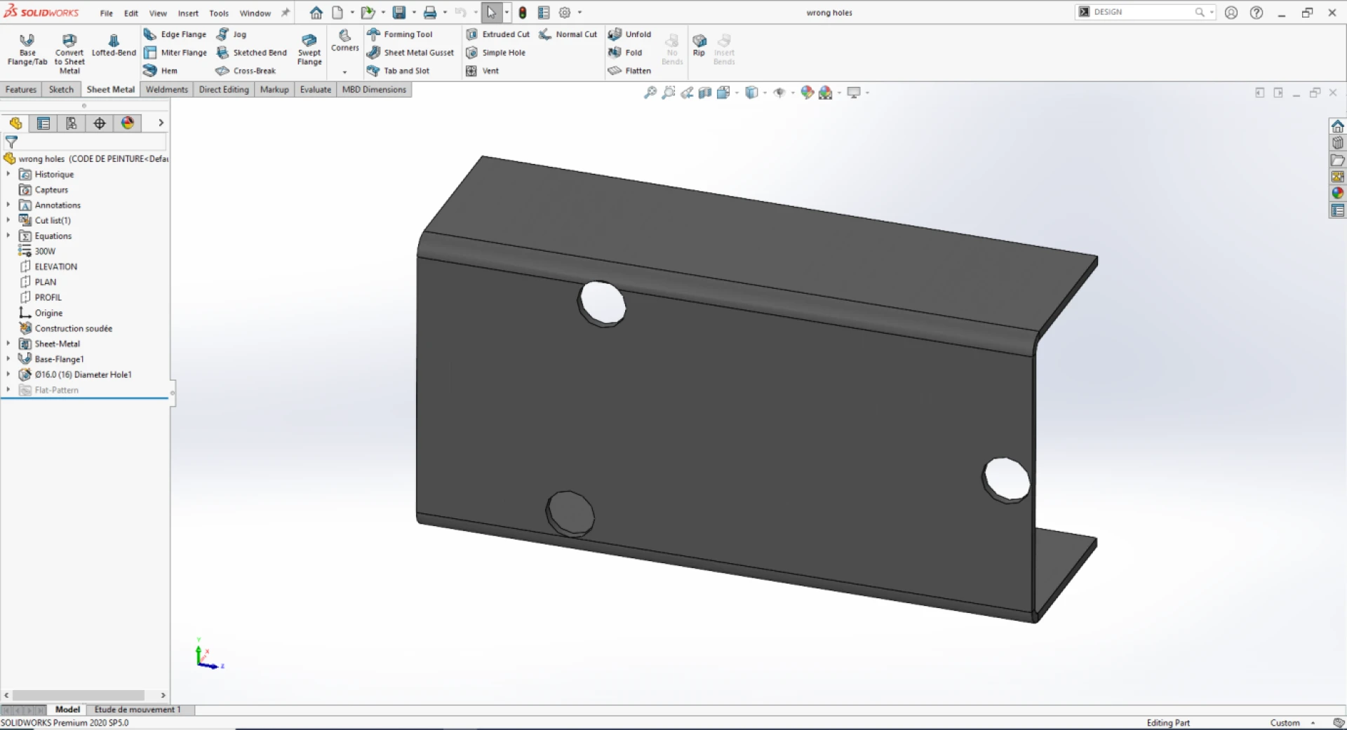
Placing holes too close to bend lines or edges can cause tearing, deformation or stress concentration during bending. This can weaken the part and lead to premature failure. Incorrect hole spacing is a common sheet metal CAD mistake.
How to avoid
• Adhere to the “4T rule,” keeping holes at least four times the material thickness away from bend lines
• For multiple holes, consider using a grid system or matrix to define their positions. This ensures consistency and simplifies dimensioning.
• Include detailed notes specifying hole characteristics (e.g., diameter, depth, type, countersink, etc.). This ensures clear communication with manufacturing.
• Define appropriate tolerances for hole locations based on the functional requirements of the part. Consider factors such as assembly fit, mating components, and manufacturing capabilities.
• Consider alternative fastening methods, like clinching or welding, if holes must be near bends
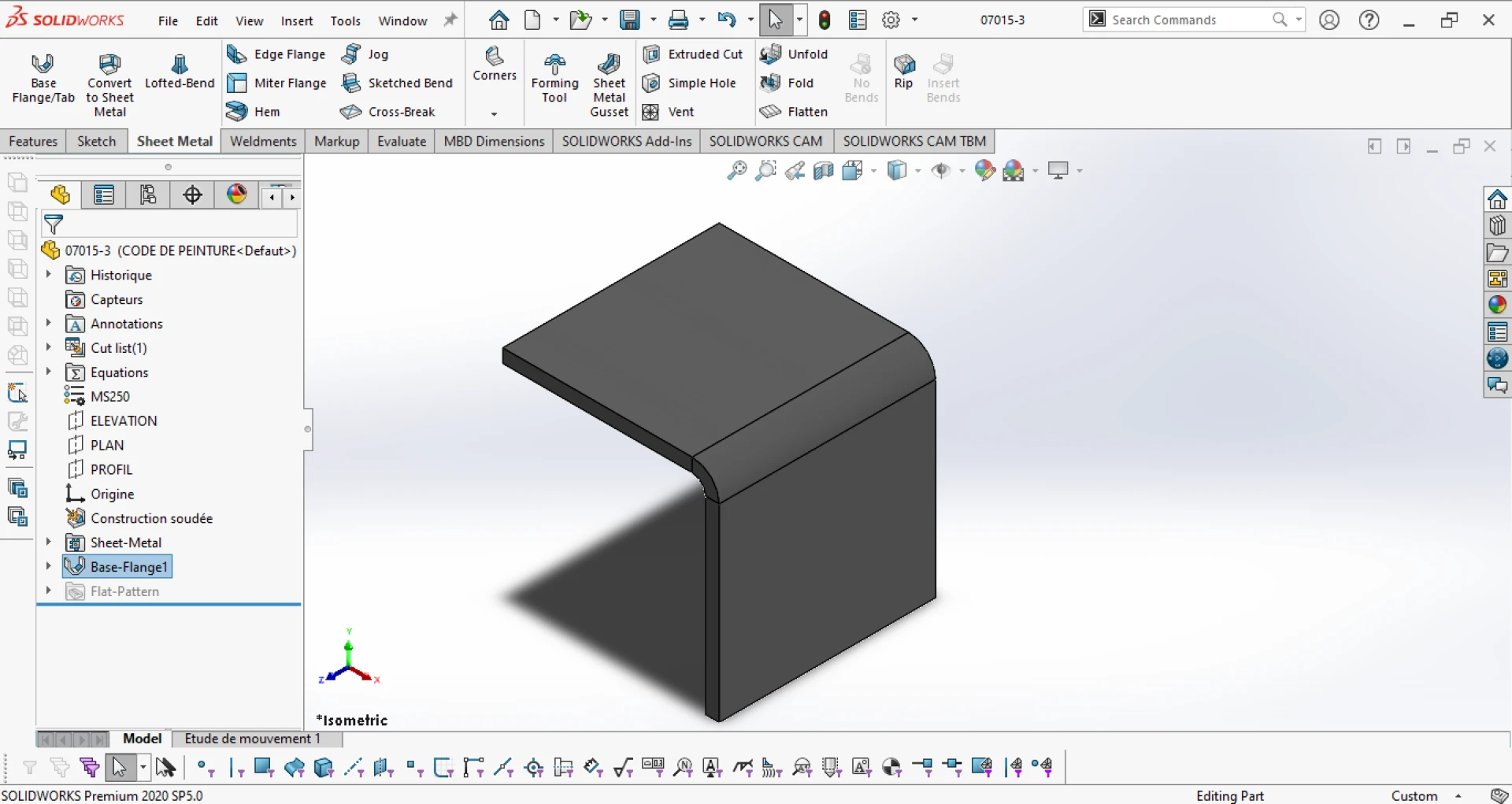
• Neglecting bend relief
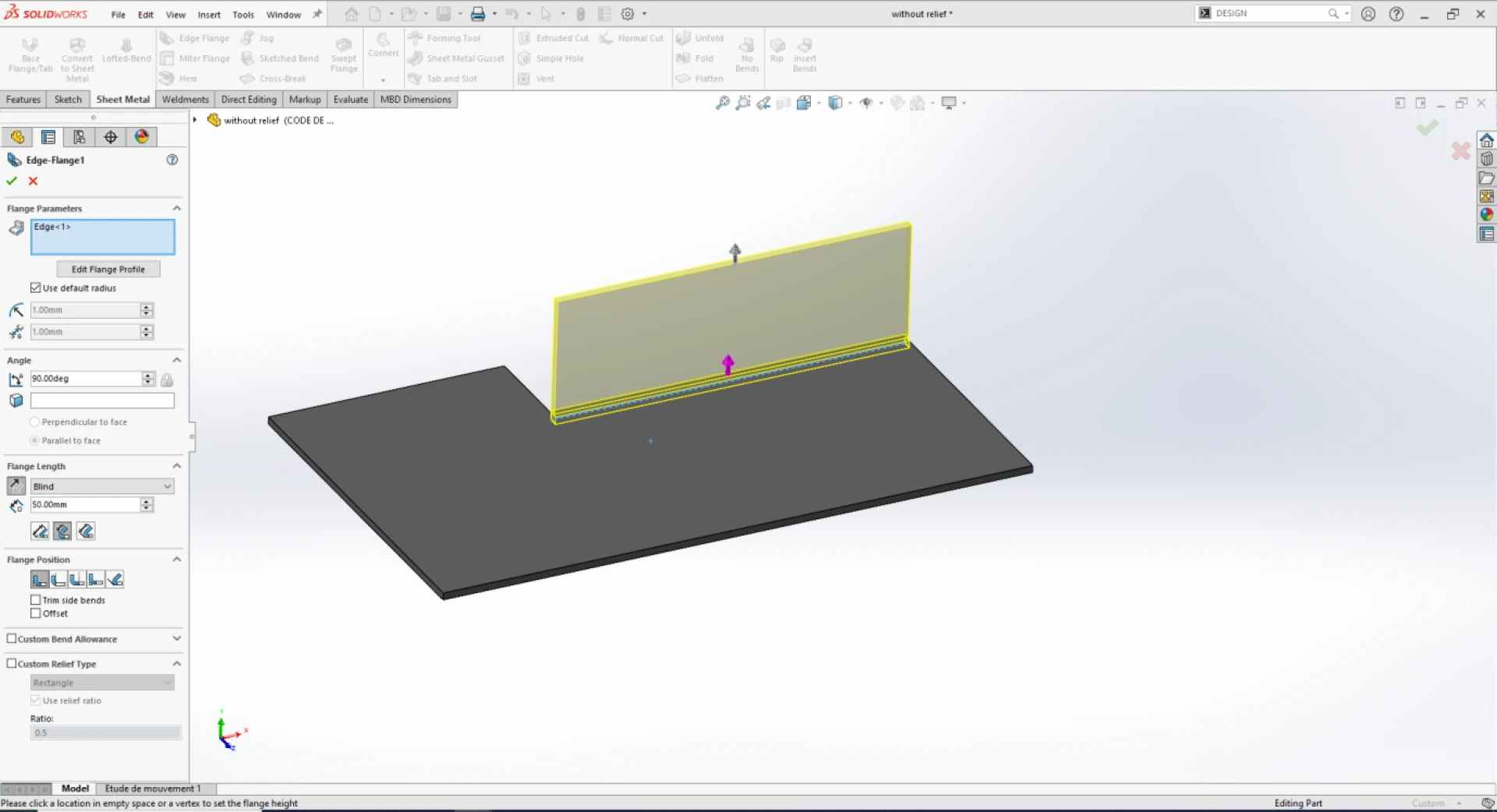
Bend relief cuts or notches are crucial to prevent tearing and distortion in areas where bends intersect with flanges or walls. Omitting bend relief can lead to stress concentration and cracking, particularly in sharp corners.
How to avoid
• Incorporate appropriate bend relief designs based on the part geometry and material thickness
• Use CAD software tools to automate bend relief generation based on predefined rules
For example, in SolidWorks, use the “Bend Relief” feature to automatically add reliefs, define parameters like relief type, size, and placement, ensuring consistent and accurate results
• Consult design guidelines and standards like those provided by the Sheet Metal and Air Conditioning Contractors’ National Association (SMACNA) for best practices
• Inadequate dimensioning and tolerance
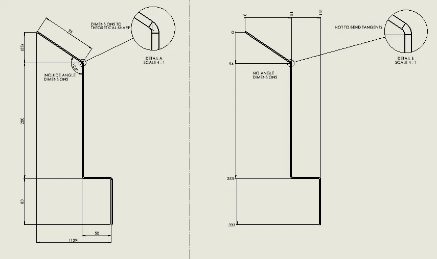
Ambiguous or incomplete dimensions and tolerances lead to misinterpretations during fabrication, resulting in parts that deviate from the intended design. This results in dimensional errors.
For instance, missing dimensions for the spacing between balusters or the tolerances for the bend angles of the handrail for designing a balustrade system can cause safety hazards, ill-fitting components, and costly rework.
How to avoid
• Apply Geometric Dimensioning and Tolerancing (GD&T) principles to ensure unambiguous communication of design intent
• Specify tolerances that are achievable within the manufacturing process capabilities to avoid unnecessary costs and delays
• Include detailed notes and specifications to clarify critical features and requirements
• Disregarding material limitations
Each sheet metal material has unique properties and limitations in terms of formability, weldability and corrosion resistance. Selecting an unsuitable material or exceeding its limitations can lead to fabrication issues and compromised product performance.
How to avoid
• Carefully consider the application requirements and environmental conditions when selecting a material
• Consult material datasheets and supplier recommendations to understand the material’s limitations and processing guidelines
• Use material selection tools and databases to compare different options and choose the most suitable material for the application
• Neglecting Design for Fabrication ( DFM)
Design for fabrication (DFM) principles are essential for creating sheet metal parts that can be fabricated efficiently and cost-effectively. Overlooking DFM considerations can result in complex designs that are difficult to produce, require specialized tooling or lead to excessive material waste.
How to avoid
• Standardization: Use standard sheet metal sizes, and thicknesses, and bend radii whenever possible to minimize material costs and lead times
• Feature accessibility: Ensure all features, such as holes, slots, and bends, are accessible with standard tooling and fabrication processes
• Simple geometry: Opt for simple, streamlined designs that minimize the number of bends, features, and complex geometries
• Collaboration: Communicate with the fabricator early in the design process to discuss DFM considerations and identify manufacturing challenges
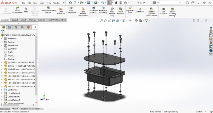
Case Study
Optimized CAD drafting for sheet metal products reduces TAT by 56%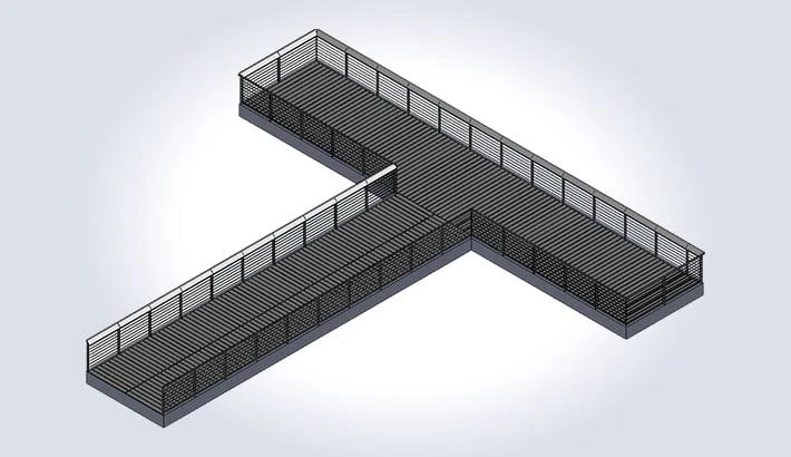
Customer Profile: A US-based fabricator specializing in sheet metal building products and electrical enclosures.
Challenges: The client provided only PDF drawings, necessitating iterative detailing for accuracy. Complex assemblies required multiple resources, and engineers needed a keen eye for manufacturing details to maintain precision.
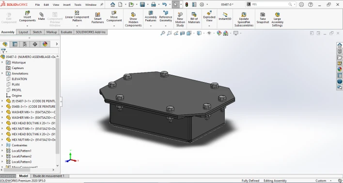
Solutions: Hitech CADD Services developed detailed 3D CAD models and manufacturing drawings using SolidWorks and AutoCAD, adhering to DFMA guidelines. By building a comprehensive product library and employing a top-down design approach, we reduced customization errors and enhanced efficiency.
Wrapping up
By avoiding these common mistakes in sheet metal drafting and implementing the suggested solutions, you ensure accurate, manufacturable designs that translate into high-quality, functional products.
Embracing best practices, using advanced CAD tools, and maintaining effective communication between drafters and sheet metal fabricators will contribute to improved efficiency, reduced costs, and enhanced product success to give you a competitive edge in the sheet metal industry.


Sign in to leave a comment.